Setting & Operation
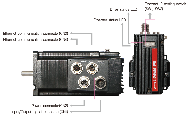
◆ M Type
◆ R Type
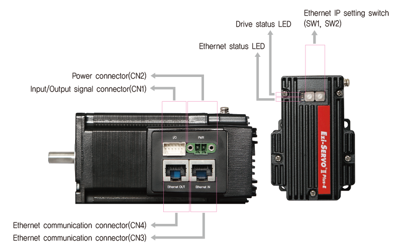
Status LED
- 1. Ethernet Status LED
- LED indicates communication status of Ethernet
-
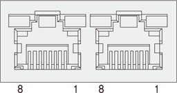
Name Color Status Explanation Link1,2 Green OFF Link deactivated ON Link activated 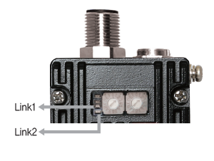
- 2. Drive Status LED
- In the case of Ezi-SERVOⅡ Plus-E ALL series products, LED can be checked by LED color, lighting, On/Off and blinking.
-
Status LED Description Disable Green :
Red :ST1 light flashing,
ST2 light offEnable Green :
Red :ST1 light on,
ST2 light offIn motion Green :
Red :ST1 light on,
ST2 light onIn-position deviation Green :
Red :ST1 and ST2
light alternately flashingAlarm Green :
Red :ST2 light flashing repeatedly
as many as alarm number 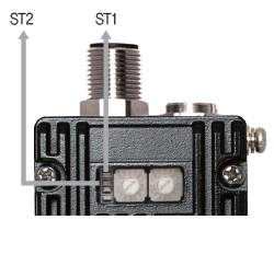
- ◆ Protection functions and LED flash times
-
Times Protection Conditions 1 Over Current Error The current through power devices in inverter exceeds the limit value*1 2 Over Speed Error Motor speed exceeds 3,000 [rpm] 3 Position Tracking Error Position error value is higher than 180˚ in motor run state*2 4 Over Load Error The motor is continuously operated more than 5 seconds under a load exceeding the max. torque 5 Over Temperature Error Inside temperature of drive exceeds 85℃ 6 Over Regeneratived Voltage Error Back-EMF is higher than limit value*3 7 Motor Connect Error The power is ON without connection of the motor cable to dre 8 Encoder Connect Error Cable connection error in Encoder connection of drive 10 In-Position Error After operation is finished, position error more than 1 pulse is continued for more than 3 seconds 12 ROM Error Error occurs in parameter storage device(ROM) 15 Position Overflow Error Position error value is higher than 180˚ in motor stop state*2 -
* 1 : Limit value depends on motor model. (Refer to the Manual)
* 2 : Default value can be changed by parameter. (Refer to the Manual)
* 3 : Voltage limit of Back-EMF depends on motor model. (Reefr to the Manual
※ Please refer to uer Manual for the details of protection functions. -
Alarm LED flash
(Ex: Position tracking error)
Switch
- 1. Ethernet IP Setting Switch(SW1, SW2)
-
It can be set the value of the fourth digit of Ethernet IP through the setting switch. Set the product’s IP not to overlap with the connected products. The first, second and third values of IP can be set through the GUI. Please refer to the manual for details. When the switch is set to 255 (FF), IP is automatically set, ignoring the setting. (DHCP function)
The fourth digit of the Ethernet IP is displayed in 7-Segment.
IIn case of SW1 : 7, and SW2 : 5
(5×16) + (7×1) = 87
IP is to be set as 192.168.0.87