Plus-E MINI Type

Settings and Operation

Switch

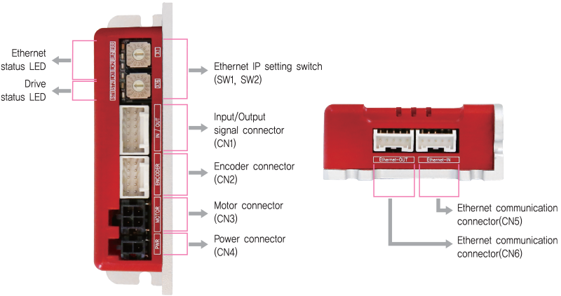
1. Ethernet IP Setting Switch(SW1, SW2)
It can be set the value of the fourth digit of Ethernet IP through the setting switch. Set the product’s IP not to overlap with the connected products. The first, second and third values of IP can be set through the GUI. Please refer to the manual for details. When the switch is set to 255 (FF), IP is automatically set, ignoring the setting. (DHCP function)

In case of SW1: 7 and SW2: 5
(5×16) + (7×1) = 87
IP is to be set as 192.168.0.87
<

Status LED

1. Ethernet Status LED
LED indicates communication status of Ethernet.
Name Color Function Explanation
ERR Red OFF No Error status
ON Local Error
LK1/
LK2
Green OFF Link deactivated
ON Link activated
RUN Orange Blinking Normally operating
2. Drive Status LED
Status LED
Disable ST1 :  
ST2 :
ST1 light flashing, ST2 light off
Enable ST1 :  
ST2 :
ST1 light on, ST2 light off
In motion ST1 :  
ST2 :  
ST1 light on, ST2 light on
Alarm ST1 :
ST2 :  
ST2 light flashing repeatedly as many as alarm number
◆ Protection functions and LED flash times
Times Protection Conditions
1 Over Current Error The current through power devices in drive exceeds 4.8A
2 Over Speed Error Motor speed exceeds 3,000 [rpm]
5 Over Temperature Error Inside temperature of drive exceeds 85℃
6 Over Regeneratived Voltage Error Back-EMF is higher than 48V
7 Motor Connect Error The drive does STEP ON without connection of the motor cable to drive.
12 ROM Error Error occurs in parameter storage device(ROM)
Alarm LED flash
(Ex, Over Speed error)

Connector

1. Input/Output Signal Connector(CN1)
NO. Function I/O
1 EXT_24VDC Input
2 EXT_GND Input
3 BRAKE+ Output
4 BRAKE- Output
5 LIMIT+ Input
6 LIMIT- Input
NO. Function I/O
7 ORIGIN Input
8 Digital In1 Input
9 Digital In2 Input
10 Digital In3 Input
11 Compare Out Output
12 Digital Out1 Output
2. Encoder Connector(CN2)
NO. Function I/O
1 A+ Input
2 A- Input
3 B+ Input
4 B- Input
5 Z+ Input
NO. Function I/O
6 Z- Input
7 5VDC Output
8 GND Output
9 F. GND ----
10 F. GND ----
3. Motor Connector(CN3)
NO. Function I/O
1 A Phase Output
2 B Phase Output
3 /A Phase Output
4 /B Phase Output
4. Power Connector(CN4)
NO. Function I/O
1 24VDC Input
2 GND Input
5. Ethernet Communication Connector(CN5, CN6)
NO. Function
1 TD+
2 TD-
3 RD+
4 RD-
5 F.GND

Connector Specifications

Connector specifications for cabling to drive.
Purpose Item Part Number Manufacturer
Ethernet Communication
(CN5, CN6)
Housing
Terminal
PAP-05V-S
SPHD-001T-P0.5
JST
Power
(CN4)
Housing
Terminal
43025-0200
43030-0001
MOLEX
Motor Drive Side
(CN3)
Housing
Terminal
43025-0400
43030-0001
MOLEX
Motor Side Housing
Terminal
5557-04R
5556T
MOLEX
Encoder Drive Side
(CN2)
Housing
Terminal
501646-1000
501648-1000(AWG 26~28)
MOLEX
Signal
(CN1)
Housing
Terminal
501646-1200
501648-1000(AWG 26~28)
MOLEX
※ Above connector is the most suitable product for the drive applied. Another equivalent connector can be used.