

Settings and Operation
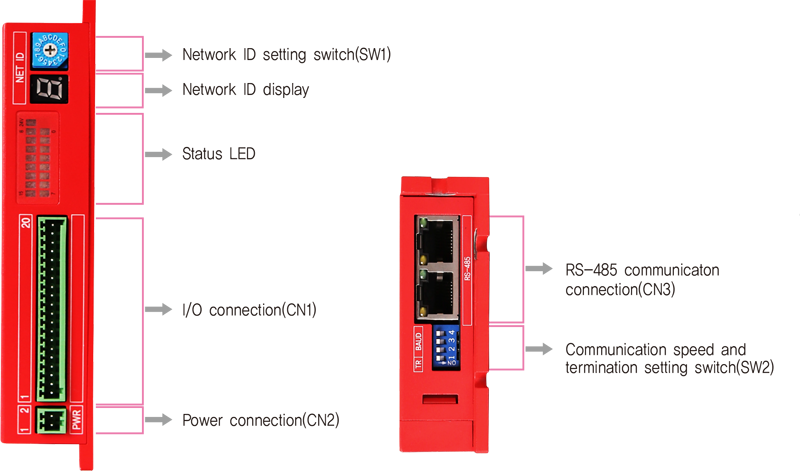
Status LED
- 1. Status LED
-
Indication Color Function ON/OFF Condition 24V Red Ext 24V Power LED is turned ON when power is applied 0~15 Green In/Out status Input On: Input signal On
Output On: Output signal On
Switch
- 1. Network ID Setting Switch(SW1)
- 1) Unique ID setting for each module
2) Total 16 number setting (0~F) -
Position ID Number 0*1 0 1 1 2 2 3 3 4 4 5 5 6 6 7 7 -
Position ID Number 8 8 9 9 A 10 B 11 C 12 D 13 E 14 F 15 -

- *1 : Default settings
- 2. Communication Speed and Termination Setting Switch(SW2)
-
Termination Setting Switch(SW2.1)
The module installed at the end of the network must be terminated for reliable operation. Please termination setting switch is ON if module installed at the end of the network.
Speed Setting Switch(SW2.2~SW2.4)
SW2.2~SW2.4 used for setting speed as follows -
SW2.1 SW2.2 SW2.3 SW2.4 Baud Rate [bps] - OFF OFF OFF 9,600 - ON OFF OFF 19,200 - OFF ON OFF 38,400 - ON ON OFF 57,600 - OFF OFF ON 115,200*1 - ON OFF ON 230,400 - OFF ON ON 460,800 - ON ON ON 921,600 -

- *1 : Default setting value
Connector
- 1. I/O Connector(CN1)
- ◆ Input Module
-
NO. Function I/O 1 EXT_24VDC Input 2 EXT_24VDC Input 3 Input0 Input 4 Input1 Input 5 Input2 Input 6 Input3 Input 7 Input4 Input 8 Input5 Input 9 Input6 Input 10 Input7 Input -
NO. Function I/O 11 Input8 Input 12 Input9 Input 13 Input10 Input 14 Input11 Input 15 Input12 Input 16 Input13 Input 17 Input14 Input 18 Input15 Input 19 EXT_GND Input 20 EXT_GND Input - ◆ Output Module
-
NO. Function I/O 1 EXT_24VDC Input 2 EXT_24VDC Input 3 Output0 Output 4 Output1 Output 5 Output2 Output 6 Output3 Output 7 Output4 Output 8 Output5 Output 9 Output6 Output 10 Output7 Output -
NO. Function I/O 11 Output8 Output 12 Output9 Output 13 Output10 Output 14 Output11 Output 15 Output12 Output 16 Output13 Output 17 Output14 Output 18 Output15 Output 19 EXT_GND Input 20 EXT_GND Input - ◆ I/O Module
-
NO. Function I/O 1 EXT_24VDC Input 2 EXT_24VDC Input 3 Input0 Input 4 Input1 Input 5 Input2 Input 6 Input3 Input 7 Input4 Input 8 Input5 Input 9 Input6 Input 10 Input7 Input -
NO. Function I/O 11 Output0 Output 12 Output1 Output 13 Output2 Output 14 Output3 Output 15 Output4 Output 16 Output5 Output 17 Output6 Output 18 Output7 Output 19 EXT_GND Input 20 EXT_GND Input 
- 2. Power Connector(CN2)
-
NO. Function I/O 1 24VDC Input 2 GND Input 
- 3. RS-485 Communication Connector(CN3)
-
NO. Function 1 GND 2 GND 3 Data+ 4 GND 5 GND -
NO. Function 6 Data- 7 GND 8 GND LED 1, 3 Module status LED 2, 4 Communication status 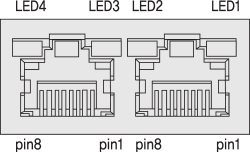
Connector Specifications
- Connector specifications for cabling to module.
-
Purpose Item Part Number Manufacturer Power
(CN2)Terminal Block ESC250V-02P DINKLE I/O
(CN1)Terminal Block ESC250V-20P DINKLE - ※ Above connector is the most suitable product for the module applied. Another equivalent connector can be used.