


Settings and Operation

-
No. Name Function ① Status Indicator LED Indicates the status of the drive. ② Motor Sensor Connector (CN4 HALL-S) Connects the motor sensor. ③ Motor Connector (CN2 MOTOR) Connects the motor power. ④ Power / Regenerative Resistor Connector (CN1) Connects the main power supply and the regenerative resistor. ⑤ EtherCAT ID Indicator (ECAT ID) Displays the node address when operating normally.
Displays the error code when an alarm occurs.⑥ EtherCAT Communication Connector
(CN10 ECAT IN)Connects to the upper EtherCAT communication-compatible device. EtherCAT Communication Connector
(CN9 ECAT OUT)Connects to the next node in sequence among EtherCAT communication-supported devices. ⑦ EtherCAT ID Setting switch (ECAT ID) Sets the node address. ⑧ USB Connector (CN8 USB) Connects the drive to a PC. ⑨ Input / Output Signal Connector (CN7 I/O) Connects input / output signals.
Status Indicator LED
- 1. Drive Status Indicator LED
-
Item Color Function Description POWER Green Power Status Lights up when power is applied. ALARM Red Alarm Status Flashes when an error occurs. - ● List of Error Types by the Number of LED Blinking
-
No. Error Type Causes 1 Overcurrent Excessive current has flown through the drive. 2 Overspeed The rotation speed of the motor output shaft exceeds approx. 120% of maximum speed. 5 Overtemperature When the internal temperature of the drive exceeds the allowable temperature. 6 Overvoltage When the back electromotive force of the motor increases and the motor driving voltage inside the drive exceeds the allowable rated voltage. 8 Hall sensor Error There is a problem with the connection between the drive and the motor sensor. 9 Undervoltage When the input power voltage is lower than allowable minimum voltage. 10 Initial Operation Inhibition Power is applied while the FWD or REV input is on. The error will operate only if the ‘No Operation at Initial Run’ parameter is set to 1. 11 System error There is a problem in the internal circuit board. 12 ROM error The stored data is damaged or the read / write of the EEPROM is failed. 15 External stop error When EXT-ERROR input is executed in direct IO (operates when EXT-ERROR input is set in direct IO). Lights
up49 Drive Alarm Occurrence When other alarms occur in the drive. 50 Drive Internal Communication Error When a timeout error occurs in the internal communication. 52 When a CRC error occurs in the internal communication. 53 When a command is not executed properly in the internal communication. 71 Network Initialization Error When an error occurs during the initialization process of communication hardware due to incorrect values written in the EEPROM. 76 Drive Internal Communication Failure When internal communication of the drive cannot be started 100 ROM Error When parameters are not properly saved in ROM 101 When the checksum of the ROM does not match 102 When an error occurs during the process of reading data from FRAM 110 When an error occurs during the process of reading data from ROM 121 When an error occurs during the process of writing data to ROM (1) 122 When an error occurs during the process of writing data to ROM (2) 123 When an error occurs during the process of writing data to ROM (3) 124 When an error occurs during the process of writing data to ROM (4) 200 ROM Data Out of Range When the parameter values stored in ROM exceed the allowable range 500 EtherCAT Communication Error When a communication error occurs during EtherCAT communication
- 2. EtherCAT Indicator LED
-
Item Color Status Description RUN 녹색 OFF When in an initialization mode or when the power is OFF. Blinking Pre-Operational mode Single Flash Safe-Operational mode ON Operational mode Flickering Bootstrap mode ERR Red OFF When no communication error has occurred or when the power is OFF. Blinking Communication setting error Single Flash Communication data error Double Flash Watchdog Timeout Link / Activity Green OFF When communication is not connected. ON When communication is connected but not yet operational. Flickering When communication is connected and operational.
Connector
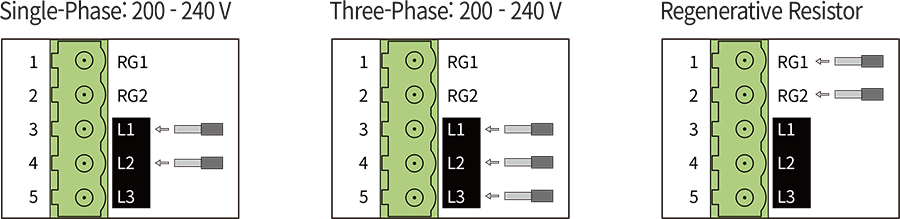
- 1. Power / Regenerative Resistor Connector (CN1)
-
No. Function 1 Regenerative Resistor Connection (RG1) 2 Regenerative Resistor Connection (RG2) 3 Power Input (L1) 4 Power Input (L2) 5 Power Input (L3) 
-
* Use RG1, RG2 terminals when connecting a regenerative resistor. A regenerative resistor can be used when the deceleration time is short or the load with large inertia is applied.
* Please refer to the manual for details of regenerative resistor specifications. - ● Connection Method
- ● Wire Specifications
- AWG18 ~ 14(0.75 ~ 2.0mm2)
- 2. Motor Connector (CN2)
-
No. Function I/O 1 - - 2 BLDC_U Output Power 3 BLDC_W Output Power 4 BLDC_V Output Power 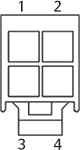
- 3. Motor sensor Connector (CN4)
-
No. Function I/O 1 DC5V Output Power 2 GND Common 3 GND Common 4 HALL_U Input 5 HALL_V Input 6 HALL_W Input 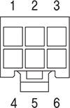
- 4. USB Connector (CN8)
-
No. Function 1 VBUS 2 D- 3 D+ 4 - 5 GND 
- ● Specification
- Standard USB cable(USB 2.0 Mini Type B)
- 5. Input / Output Signal Connector (CN7)
-
No. Function I/O 1 HCOM Input 2 IN0 Input 3 IN1 Input 4 IN2 Input 5 IN3 Input 6 IN4 Input 7 IN5 Input 8 IN6 Input 9 LCOM Common 10 OUT0+ Output 11 OUT0- Output 12 OUT1+ Output 13 OUT1- Output 14 VH Input 15 VM Input 16 VL Input 17 - - 18 - - 19 - - 20 - - 
- 6. EtherCAT Communication Connector (CN9, CN10)
-
No. Function Description 1 TD+ Transmission Data+ 2 TD- Transmission Data- 3 RD+ Reception Data+ 4 N.C. Not connected 5 N.C. Not connected 6 RD- Reception Data- 7 N.C. Not connected 8 N.C. Not connected 9 FG Frame Ground 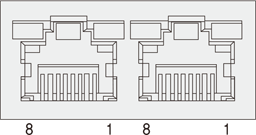
Accessories - Connectors
- These are connector specifications for drive cabling.
-
Purpose Item Part Number Manufacturer Power (CN1) Terminal Block CPF5.08-05P STELVIO Motor (CN2) Drive Side (CN2) Housing 5557-04R MOLEX Terminal 5556T Motor Side Housing 5559-04P MOLEX Terminal 5558T Sensor (CN4) Drive Side (CN4) Housing 5557-06R MOLEX Terminal 5556T Sensor Side Housing 5559-06P MOLEX Terminal 5558T Signal (CN7) Housing PADP-20V-1S JST Terminal SPH-002T-P0.5L