Status LED
- 1. Status LED
-
Indication Color Function On/Off Condition ENABLE Green Drive activated The motor of the drive connected to the motion gate is activated(Servo On or Step enable) ALARM Red Drive alarm status Alarms on connected drives CONNECT Green Drive connection status Motor drive is operating normally with the “CONNECT” command ERROR Red Drive connection error Communication error occurred during “CONNECT” command of motor drive
- 2. PROFINET Status LED
-
Indication Color Function On/Off Condition NS Green PROFINET Network status Show network connection status Red PROFINET ERROR 1 Network operation error occurred MS Green PROFINET Module status PROFINET connection status and MotionGate power status Red PROFINET ERROR 1 A PROFINET setup error occurred
- 3. PROFIBUS Status LED
-
Indication Color Function On/Off Condition RUN Green PROFIBUS Status Indicating connected PROFIBUS network status ERROR Red PROFIBUS exceptional error Data setting error occurred with master controller POWER Green Network connection status PROFIBUS network connection status and motion gate power status BF Red PROFIBUS setting error PROFIBUS parameter setting error
- 4. Device/Net Status LED
-
Indication Color Function On/Off Condition NS Green Network status Indicating the active status of the DeviceNet master controller Red when it can not communicate with DeviceNet master controller MS Green Module Statu Indicating the status of the DeviceNet network of the motiongate. Red Indicating the DeviceNet network error of motion gate
- 5. Ethernet/IP Status LED
-
Indication Color Function On/Off Condition NS Green Network status Indicating the EtherNet/IP connection status of master controller Red IP address error and no communication with master controller MS Green Module Status Indicating the detected status of the EtherNet/IP network of the host controller Red EtherNet/IP network device error
- 6. Ethernet Status LED
-
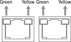
Name Color Status Explanation LINK /
ActivityGreen ON 100 [Mbps] Link setting status Flickering 100 [Mbps] Link activated Yellow ON 10 [Mbps] Link setting status Flickering 10 [Mbps] Link activated 
Switch
- 1. PROFIBUS Network ID Setting Switch(SW1, SW2, SW3)
-
Number
(SW3)ID number×100
(100 digit)Number
(SW2)ID number
×10(10 digit)Number
(SW1)ID number
×1(1 digit)0 000 0 00 0 0 1 100 1 10 1 1 1 ---- 2 20 2 2 3 ---- 3 30 3 3 4 ---- 4 40 4 4 5 ---- 5 50 5 5 6 ---- 6 60 6 6 7 ---- 7 70 7 7 8 ---- 8 80 8 8 9 ---- 9 90 9 9 
- 2. DeviceNet Network ID Setting Switch(SW1, SW2)
-
Number
(SW2)ID number
×10(10 digit)Number
(SW1)ID number
×1(1 digit)0 00 0 0 1 10 1 1 2 20 2 2 3 30 3 3 4 40 4 4 5 50 5 5 6 60 6 6 7 ---- 7 7 8 ---- 8 8 9 ---- 9 9 
- 3. DeviceNet Network Speed Setting Switch
-
Number(SW3) Baud Rate [kbps] 0 125 1 250N 2 500 3 Auto Baud Rate 4···9 ----
- 4. PROFINET, Ethernet/IP Network ID/Speed setting Switch(SW1, SW2, SW3)
- There are no configurable function currently.
- 5. Communication Speed and Termination Setting Switch(SW4)
-
Termination Setting Switch(SW4.1)
The drive installed at the end of the network must be terminated for reliable operation. Please termination setting switch is ON if drive installed at the end of the network.
Speed Setting Switch(SW4.2~SW4.4)
SW4.2~SW4.4 used for setting speed as follows -
SW4.1 SW4.2 SW4.3 SW4.4 Baud Rate [bps] - OFF OFF OFF 9,600 - ON OFF OFF 19,200 - OFF ON OFF 38,400 - ON ON OFF 57,600 - OFF OFF ON 115,200*1 - ON OFF ON 230,400 - OFF ON ON 460,800 - ON ON ON 921,600 -

- *1 : Default setting value
Connector
- 1. Power Connector(CN1)
-
NO. Function I/O 1 24VDC Input 2 GND Input 
- 2. RS-485 Communication Connector(CN2)
-
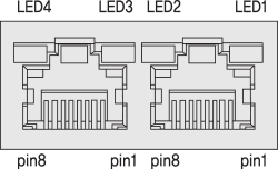
NO. Function 1 GND 2 GND 3 Data+ 4 GND 5 GND -
NO. Function 6 Data- 7 GND 8 GND LED 1, 3 Receiving status LED 2, 4 Transmission status 
- 3. PROFIBUS DP connector(CN3)
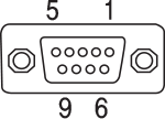
- Network connection connector compatible with PROFIBUS DP.
-
NO. Function I/O 1 ---- ---- 2 ---- ---- 3 B Line Input/Output 4 RTS. Input/Output 5 GND Input/Output 6 5v Power output(60mA) 7 NC ---- 8 A Line Input/Output 10 ---- ---- 
- ※ The connection to the PROFIBUS cable, we recommend using a dedicated cable connector for DP.
- 4. DeviceNet connector(CN3)
- The power of the motion gate is used independently with the bus power of the DeviceNet cable. If only the power of the DeviceNet connector is supplied, the power of the motion gate will not turn ON. Also, it will not work if DeviceNet bus power is not supplied to the network connector of the motion gate.
-
NO. Function Color 1 GND Black 2 CAN_L Blue 3 DRAIN Shield 4 CAN_H White 5 24VDC Red 
- ※ It is recommended to use dedicated DeviceNet cable.
- 5. PROFINET, EtherNet/IP Connector(CN3, CN4)
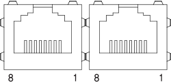
- The PROFINET, EtherNet/IP network is compatible with Ethernet cables manufactured by TIA/EIA-568-B(T568B).
-
NO. Function 1 TD+ 2 TD- 3 RD+ 4 ---- 5 ---- -
NO. Function 6 RD- 7 ---- 8 ---- Connection
hoodF.GND - ※ It is recommended to use Category 5e or more of STP/FTP cable.


