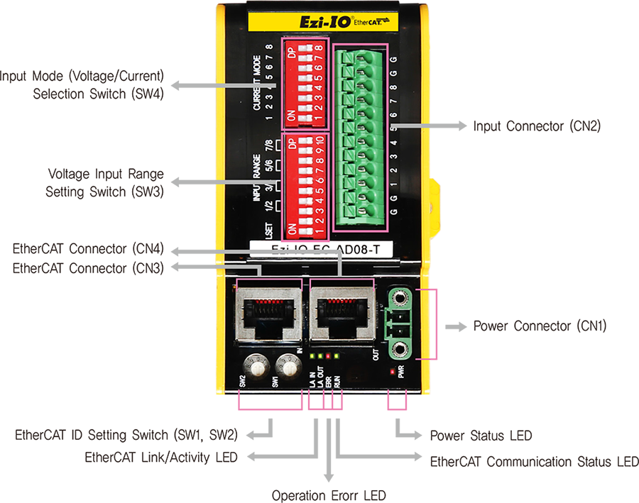
Ezi-IO-EC-AD08-T
Settings and Operation

Switch
- 1. Ethernet IP Display and Setting Switch(SW1, SW2)
- Use two rotary switches to set EtherCAT ID (ECAT Device ID). Set ones digit (x1) of EtherCAT ID on the right rotary switch (SW1), and set tens digit (x10) of EtherCAT ID on the left rotary switch (SW2).

- 2. Input Mode (Voltage/Current) Selection Switch (SW4)
- Select either Voltage or Current Input Mode for each channel with SW4 referring to the chart.

-
CH1 CH2 CH3 CH4 CH5 CH6 CH7 CH8 SW4.1 SW4.2 SW4.3 SW4.4 SW4.5 SW4.6 SW4.7 SW4.8 Mode Voltage Input OFF OFF OFF OFF OFF OFF OFF OFF Current Input ON ON ON ON ON ON ON ON - *Select the input mode for each channel with the Input Mode Selection Switch(SW4) before supplying power to the module.
- 3. Voltage Input Range Setting Switch(SW3)
- Select the voltage input range by SW3 referring to the chart. Analog signals are converted to the digital data according to the selected range of input voltage.

- Select the input setting method with the LSET (SW3.1) switch.
[ Selecting Input Setting Method ] -
LSET Description SW3.1 Setting Method DIP Switch ON Setting voltage input range with DIP switches
(SW3.3~SW3.10)SDO Communication OFF Setting voltage/current input range through
EtherCAT SDO communication - * If you use any channel in curernt input mode, select the SDO Communication ofr setting method (SW3.1=OFF).
* Set SW3.1 before supply power to the module.
* SW3.2 is not used.
- When using the DIP Switch for setting method (SW3.1= ON), select voltage input range referring to the chart.
[ Selecting Voltage Input Range ] -
CH1/CH2 CH3/CH4 CH5/CH6 CH7/CH8 SW3.3 SW3.4 SW3.5 SW3.6 SW3.7 SW3.8 SW3.9 SW3.10 Input
Range-10~10V OFF OFF OFF OFF OFF OFF OFF OFF -5~5V OFF ON OFF ON OFF ON OFF ON -2.5~2.5V ON OFF ON OFF ON OFF ON OFF 0~10V ON ON ON ON ON ON ON ON
Status LED
- 1. Status Monitor LED
-
Name Color Function Explanation PWR Red OFF Power is OFF ON Power is ON RUN Green OFF State INIT or Power OFF Blinking State PRE-OPERATIONAL Single Flash State SAFE-OPERATIONAL ON State OPERATIONAL Flickering State BOOTSTRAP -
Name Color Function Explanation ERR Red OFF No Error or Power OFF Blinking Invalid Configuration Single Flash Local Error Double Flash Watchdog Time Out Link /
ActivityGreen OFF Link not Established ON Link Established Flickering Link Established and in Operation
Connector
- 1. Power Connector(CN1)
-
NO. Function I/O 1 DC24V Input 2 GND Input 
- *Supply rated power source to the connector.
- 2. Input Connector(CN2)
-
NO. Function I/O 1 GND Input 2 GND Input 3 Analog In 1 Input 4 Analog In 2 Input 5 Analog In 3 Input 6 Analog In 4 Input 7 Analog In 5 Input 8 Analog In 6 Input 9 Analog In 7 Input 10 Analog In 8 Input 11 GND Input 12 GND Input 
- 3. EtherCAT Communication Connector(CN3, CN4)
-
NO. Function 1 TD+ 2 TD- 3 RD+ 4 ---- 5 ---- -
NO. Function 6 RD- 7 ---- 8 ---- Connector
hoodF.GND 
Connector Specifications
- Connector specifications for cabling to module.
-
Purpose Item Part Number Manufacturer Power (CN1) Terminal Block MC421-38102 DECA - ※ The connector above is the most suitable model for Ezi-IO EtherCAT AD. Another equivalent connector can be used.


