


Setting & Operation
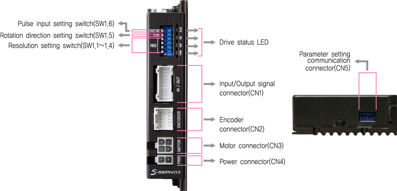
Status Monitor LED
- 1. LED Display
-
Indication Color Function ON/OFF Condition PWR Green Power Input Indication LED is turned ON when power is applied INP Yellow Complete positioning motion Light on when Position Deviation located within preset value*1 from target position, after Position Command Pulse Input is completed EN Orange Motor Enable Status Enable: Lights On, Disable: Lights Of ALM Red Alarm Indication Flash when protection function is activated (Identifiable which protection mode is activated by counting the blinking times) -
- * 1 : Default = 0. Can be selected by parameter setting GUI
- ◆ Protection functions and LED flash times
-
Times Protection Conditions 1 Over Current Error The current through power devices in drive exceeds 4.8A 2 Over Speed Error Motor speed exceed 3,000 [rpm] 3 Position Tracking Error Position error value is higher than 180˚ in motor run state 4 Over Load Error The motor is continuously operated more than 5 second under a load exceeding the max. torque 5 Over Temperature Error Inside temperature of drive exceeds 85℃ 6 Over Regenerated Voltage Error Back-EMF more than 48V 7 Motor Connection Error The power is ON without connection of the motor cable to drive 8 Encoder Connect Error Cable connection error in Encoder connection of drive 10 In-Position Error After operation is finished, position error more than 1 pulse is continued for more than 3 seconds 12 ROM Error Error occurs in parameter storage device(ROM) 15 Position Overflow Error Position error value is higher than 180˚ in motor stop state -
Alarm LED flash
(Ex, Position tracking error)
Switch
- 1. Resolution Selection Switch(SW1.1~SW1.4)
- The Number of pulse per revolution.
-
Position Pulse/Revolution 1 2 3 4 ON ON ON ON 500 ON ON ON OFF 1,000 ON ON OFF ON 1,600 ON ON OFF OFF 2,000 ON OFF ON ON 3,200 ON OFF ON OFF 3,600 ON OFF OFF ON 4,000 ON OFF OFF OFF 5,000 OFF ON ON ON 6,400 OFF ON ON OFF 8,000 OFF ON OFF ON 10,000*1 OFF ON OFF OFF 20,000 OFF OFF ON ON 25,000 OFF OFF ON OFF 36,000 OFF OFF OFF ON 40,000 OFF OFF OFF OFF 50,000 -
- * It is ship out to be set to the same resolution as the encoder.
*1 : In case of products with an encoder resolution of 16,000, the corresponding pulse/rotation is 16,000.
- * It is ship out to be set to the same resolution as the encoder.
- 2. Rotational Direction Selection Switch(SW1.5)
-
Indication Switch Name Function DIR Switching Rotational Direction Based on CW(+Dir signal) input to driver.
ON: CCW(-Direction)
OFF: CW(+Direction)
※ Default: CW mode 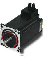
CCW Direction
Direction setting switch : ON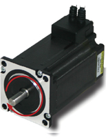
CW Direction
Direction setting switch : OFF
- 3. Pulse Input Selection Switch(SW1.6)
-
Indication Switch Name Function 2P/1P Selecting Pulse Input Mode Selectable 1-Pulse input mode or 2-Pulse input mode as Pulse input signal.
ON: 1-Pulse mode
OFF: 2-Pulse mode
※ Default: 2-Pulse mode 
Connector
- 1. Power Connector(CN4)
-
No. Function I/O 1 24VDC Input 2 GND Input 
- 2. Motor Connector(CN3)
-
No. Function I/O 1 A Phase Output 2 B Phase Output 3 / A Phase Output 4 / B Phase Output 
- 3. Encoder Connector(CN2)
-
No. Function I/O 1 A+ Input 2 A- Input 3 B+ Input 4 B- Input 5 Z+ Input 6 Z- Input 7 5VDC Output 8 GND Output 9 F.GND ---- 10 F.GND ---- 
- 4. Input/Output Signal Connector(CN1)
-
No. Function I/O 1 A- Output 2 A+ Output 3 B- Output 4 B+ Output 5 Z- Output 6 Z+ Output 7 BRAKE- Output 8 BRAKE+ Output 9 EXT_GND Input 10 EXT_24VDC Input -
No. Function I/O 11 Alarm Reset Input 12 Enable Input 13 Alarm Output 14 In-Position Output 15 O.C Input Input 16 S-GND Output 17 CW-(Pulse-) Input 18 CW+(Pulse+) Input 19 CCW-(Dir-) Input 20 CCW+(Dir+) Input 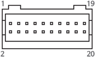
- 5. Parameter Setting Connector(CN5)
-
No. Function I/O 1 Tx Output 2 Rx Input 3 GND ---- 
Connector Specifications
- Connector specifications for cabling to drive.
-
Purpose Item Part Number Manufacture I/O
(CN1)Housing
TerminalPADP-20V-1-S
SPH-002T-P0.5LJST Encoder Drive Side
(CN2)Housing
Terminal51353-1000
56134-9000MOLEX Encoder Side Housing
TerminalSMP-09V-NC
SHF-001T-0.8BSJST Motor Drive Side
(CN3)Housing
Terminal5557-04R
5556TMOLEX Motor Side Housing
Terminal5557-04R
5556TMOLEX Power
(CN4)Housing
Terminal5557-02R
5556TMOLEX - ※ Above connector is the most suitable product for the drive applied. Another equivalent connector can be used.