


Input Signal
- Input signals of the drive are all photocoupler protected. The signal shows the status of internal photocouplers [ON: conduction], [OFF: Non-conduction], not displaying the voltage levels of the signal.

-
Functions Pin Number S-SERVOⅡ ST S-SERVOⅡ MINI Open Collector Input 15 15 CW+ 18 1 CW- 17 2 CCW+ 20 3 CCW- 19 4 - ※ S-SERVOⅡ 2X and 3X’s pin number is the same as S-SERVOⅡ ST.
- ◆ CW, CCW Input
-
This signal can be used to receive a positioning pulse command from a user host motion controller. The user can select 1-pulse input mode or 2-pulse input mode.
The input schematic of CW, CCW is designed for 5V TTL level. When using 5V level as an input signal, the resistor Rx is not used and connect to the driver directly. When the level of input signal is more than 5V, Rx resistor is required. If the resistor is absent, the drive will be damaged. If the input signal level is 12V, Rx value is 680ohm and 24V, Please use Open Collector Input.

-
Functions Pin Number S-SERVOⅡ ST S-SERVOⅡ MINI EXT_24VDC 10 20 Alarm Reset 11 14 Enable 12 13 - ※S-SERVOⅡ 2X and 3X’s pin number is the same as S-SERVOⅡ ST.
- ◆ Enable Input
- This input can be used only to adjust the position by manually moving the motor shaft from the load-side. By setting the signal [ON], the driver cuts off the power supply to the motor. Then, one can manually adjust output position. When setting the signal back to [OFF], the driver resumes the power to the motor and recovers the holding torque. When driving a motor, one needs to set the signal [OFF].
- ◆Alarm Reset Input
- When a protection mode has been activated, a signal to this alarm reset input cancels the Alarm output.

- ※ By setting the alarm reset input signal [ON], cancel the Alarm output. Before cancel the Alarm output, have to remove the source of alarm.
Output Signal
- Output signals from the driver are photocoupler protected: Alarm, In-Position. The signal indicates the status of internal photocouplers [ON: conduction], [OFF: Non-conduction], not displaying the voltage levels of the signal.

-
Functions Pin Number S-SERVOⅡ ST S-SERVOⅡ MINI Alarm 13 11 In-Position 14 12 EXT_GND 9 19 - ※ S-SERVOⅡ 2X and 3X’s pin number is the same as S-SERVOⅡ ST.
- ◆ Alarm Output
- The Alarm output indicates [ON] when the driver is in abnormal operation. If a protection mode has been activated, it goes [OFF]. A host controller needs to detect this signal and stop sending a motor driving command. When the driver detects an abnormal operation such as overload or over current of the motor, it sets the Alarm output to [OFF], flashes the Alarm LED, disconnect the power to a motor and stops the motor simultaneously
- [Caution]] Only at the Alarm output port, the photocoupler isolation is in reverse. When the driver is in normal operation the Alarm output is [ON].
- ◆ In-Position Output

- In-Position signal is [ON] when positioning is completed. This signal is [ON] when the motor position error is within the value set by the switch SW4.
Parameter Settings GUI
[User Interface]
-
S-SERVOⅡ driver utilizes various parameters for operation.
Some parameters need to be adjusted once users feel inconvenience to use or in order to maximize efficiency.
S-SERVOⅡ provides parameter modification program for convenience of product usage for users.
The screen shot as below is computer program (GUI) which used for operation process. Users can change and set the parameters of drive for Enable Level, Alarm Reset Level, In-Position Level, Alarm Output Level. Users can use S-SERVOⅡ according to its own system.
Please connect parameter setting GUI when S-SERVOⅡ is Disable state.
For safety reason, S-SERVOⅡ can not be connected to setting GUI when it is Enable state. 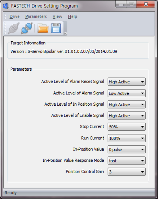
- ※ Graphic User Interface(GUI) Program can be downloaded from website. (www.fastech-motions.com)
- ※ Graphic User Interface(GUI) Program can support Window 7/8/10.
- ※ Graphic User Interface(GUI) Program can be update without prior notice for improving the performance or convenience of user.