
Settings and Operation
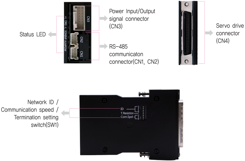
Status LED
- 1. Status LED
-
Indication Color Function ON/OFF Condition POW Green Power input indication LED is turned ON when power is applied ALM Red Alarm indication Lights when alarm occurs at Servo Drives INP Yellow Complete positioning motion Lights when position deviation is within In-Position value which set as parameter of Servo Drive after completion of position command pulse input. SON Orange Servo On/Off indication Servo On: Lights On, Servo Off: Lights Off -L Green Indicate -Limit sensor detection Lights when -Limit sensor is detected ORG Green Indicate Origin sensor detection Lights when Origin sensor is detected +L Green Indicate +Limit sensor detection Lights when +Limit sensor is detected
Switch
- 1. Network ID Setting Switch(SW1.5~1.8)
-
SW 1.8 SW 1.7 SW 1.6 SW 1.5 ID OFF OFF OFF OFF 0 OFF OFF OFF ON 1 OFF OFF ON OFF 2 OFF OFF ON ON 3 OFF ON OFF OFF 4 OFF ON OFF ON 5 OFF ON ON OFF 6 OFF ON ON ON 7 ON OFF OFF OFF 8 ON OFF OFF ON 9 ON OFF ON OFF 10 ON OFF ON ON 11 ON ON OFF OFF 12 ON ON OFF ON 13 ON ON ON OFF 14 ON ON ON ON 15
- 2. Communication Speed Setting Switch(SW1.1~1.3)
-
SW 2.1 SW 2.2 SW 2.3 ID OFF OFF OFF 9,600 OFF OFF ON 19,200 OFF ON OFF 38,400 OFF ON ON 57,600 ON OFF OFF 115,200 *1 ON OFF ON 230,400 ON ON OFF 460,800 ON ON ON 921,600 -
- * 1 : Default setting value
- 3. Termination Setting Switch(SW1.4)
- The drive installed at the end of the network must be terminated for reliable operation. Please termination setting switch is ON if drive installed at the end of the network
Connector
- 1. RS-485 Communication Connector(CN1, CN2)
-
NO. Function 1 Data+ 2 Data- 3 GND 
- 2. Servo Drive Connector(CN4)
- Pin Map of connector(CN4) which connects to Servo Drives is various according to type of Servo Drives. Please check Manual in detail. (It is plug-in to Servo Drives which are using normally so users do not have to concern.

- 3. Power Input/Output Signal Connector(CN3)
-
NO. Function I/O 1 24VDC Input 2 GND Input 3 F.GND ---- 4 BRAKE Output 5 LIMIT+ Input 6 LIMIT- Input 7 ORIGIN Input 8 Digital In1 Input -
NO. Function I/O 9 Digital In2 Input 10 Digital In3 Input 11 Digital In4 Input 12 Digital In5 Input 13 Compare Out Output 14 Digital Out1 Output 15 Digital Out2 Output 16 Digital Out3 Output