Hybrid Stepper Linear Actuator Overview
-
NEMA Size Available Versions Motor Length & Available Currents (Voltage) Max.Thrust Recommended Load Limit*1 Screw Lead Range 1.8 Degree NEMA8 Stepper 
Single Stack(27mm) :
0.5A(2.5V)78N
(17.5lbs)43N
(9.7lbs)0.012” ~ 0.315”
(0.30mm ~ 8.00mm)Double Stack(38mm) :
0.5A(4.4V)84N
(18.9lbs)1.8 Degree NEMA11 Stepper 
Single Stack(34mm) :
0.5A(4.5V), 1.0A(2.2V)230N
(51lbs)150N
(34lbs)0.025” ~ 0.400”
(0.635mm ~ 10.16mm)Double Stack(45mm) :
0.95A(3.9V)340N
(76lbs)1.8 Degree NEMA14 Stepper 
Single Stack(34mm) :
0.5A(6.6V), 1.0A(3.3V), 1.5A(2.2V)450N
(100lbs)230N
(52lbs)0.024” ~ 0.500”
(0.6096mm ~ 12.7mm)Double Stack(46mm) :
0.5A(12.0V), 1.0A(6.0V), 1.5A(4.0V)610N
(135lbs)1.8 Degree NEMA17 Stepper 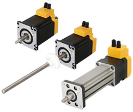
Single Stack(34mm) :
0.5A(7.2V), 1.0A(3.6V), 1.5A(2.4V)710N
(160lbs)230N
(52lbs)0.024” ~ 0.500”
(0.6096mm ~ 12.7mm)Double Stack(48mm) :
0.5A(11.0V), 1.2A(4.5V), 2.5A(2.2V)900N
(200lbs)1.8 Degree NEMA23 Stepper 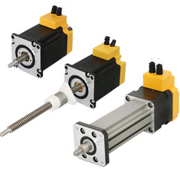
Single Stack(45mm) :
1.0A(6.4V), 2.0A(3.2V), 3.0A(2.1V)1400N
(315lbs)920N
(210lbs)0.025” ~ 1.000”
(0.635mm ~ 25.4mm)Double Stack(65mm) :
1.0A(10.8V), 2.5A(4.2V), 4.0A(2.4V)1800N
(405lbs)1.8 Degree NEMA34 Stepper 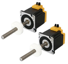
Single Stack(76mm) :
1.3A(12.0V), 3.0A(5.1V), 5.5A(2.85V)2400N
(540lbs)2160N
(485lbs)0.100” ~ 1.000”
(2.54mm ~ 24.4mm) - *1 : These are nominal load limits. Operating above these limits may decrease useful life of the system.
Technology Overview
- One of the most common methods of moving a load from point A to point B is through linear translation of a motor by a mechanical lead screw and nut. This section is here to ass ist and refresh your understanding of the basic principles of lead screw technology prior to selecting the system t hat is best for your application. Please also reference the Glossary (page 85 of the catalog) to support your understanding.
Some basic design considerations are as follows :
- 1. What is the load of your system?
- 2. What is the required speed to go from point A to point B?
- 3. What is the distance you need to travel?
- 4. What is the required time to move from point A to point B?
- 5. What accuracy does your application require?
- 6. What repeatability does your application require?
- 7. Horizontal vs vertical orientation?
Glossary
-
Accuracy The difference between the actual distance travelled versus the theoretical distance travelled based on the lead Axial Load A load that is exerted at the center line of the screw Backdriving Freewheeling of the nut and screw as a result of the load pushing axially on the screw Backlash The relative axial movement between the screw and nut Chopper Drive A constant current drive is usually bipolar. The chopper drive gets its name from the technique of rapidly switching the power on and off to control motor current. A chopper drive allows a step motor to maintain greater torque of force at higher speeds. Column Strength The ability of a screw to withstand a load in compression. Critical Speed The rotational speed of the screw at which the first harmonic of resonance is reached. Drag Torque The amount of torque to overcome the friction of a system. Dynamic Load Load applied to the screw while in motion. Efficiency The ability of a mechanical system to translate an input to an equal output. Fixity (End) The method by which the ends of the screw secured or supported. Lead The linear travel at one revolution of the screw Left Hand Thread Counter clockwise rotation Pitch The axial distance between threads Radial Load A load exerted at 90 degrees or perpendicular to a screw Repeatibility The capability of a screw and nut system to reach the same commanded position continously Resolution Incremental linear distance the actuator’s (motor) output shaft will move per input pulse Respnance Vibration occuring when a system is a mechanical system is in an unstable range Right Hand Thread Clockwise rotation Side Loading Same as a radial load (very undesirable) Static Load Load applied to the screw at standstill Straightness Linear uniformity of a screw. Total Indicated Runout A measurement of the amount of straightness of a screw. Tavel per Step Linear translation of one full step of the motor.
An Explanation of the Basics
- 1. Leads vs Pitch
- 리드 : 스크류 나사가 한 바퀴 전진하는 축 방향거리
- 피치 : 인접한 나사 사이의 축 방향 거리
- Pitch is the axial distance between threads. Pitch is equal to lead in a single start screw. Unless otherwise noted, all lead screws in this catalog are single start. Lead is the axial distance the nut advances on one revolution of the screw. Throughout this catalog, lead will be the term used for specifying a screw as it is the linear distance travelled for one revolution of the screw. The larger the lead, the more linear distance travelled per one revolution of the screw.
- 2. Load
- Typically quanti fied as either lbs or Kg to move or pounds force(lbsF) or KgF for thrust.
- 3. Velocity(V)
- Typically quanti fied as either inches/second (mm/sec) required for your application.
- 4. Distance
- Typically quanti fied as either inches or mm, is the required move distance.
- 5. Time(t)
- Typically quanti fied in seconds. Time period required for a given distance defines the velocity, acceleration (A), and deceleration needed to reach commanded position.
- 6. Horizonal or Vertical Application
- Vertical orientation applications add the potential problem of backdriving when power to the motor is off and without an installed brake. Vertical applications also have an additional gravity factor that must be part of the load/force calculation.
- 7. Accuracy of Screw
- Specified as a measurement over a given length of the screw. For example: 0.0006 in per inch. Lead accuracy is the difference between the actual distance travelled versus the theoretical distance travelled based on the lead. For example: A screw with a 0.5 inch lead and 0.004 inch per foot lead accuracy rotated 24 times theoretically moves the nut 12 inches. However, with a lead accuracy of 0.004 inch per foot, actual travel could be from 11.996 to 12.004 inches.
- 나사의 중심선을 기준으로한 ‘흔들림’의 양
- 8. Total Indicated Runout
- The amount of wobble around the centerline of the screw.
- 9. Repeatibility
- Most motion applications put the most significance on the repeatability(vs accuracy of screw) of a system to reach the same commanded position over and over again. For example: A repeatability of ± 0.005 inch means that after repeated commands to reach the same target position, the linear error will be no more than ± 0.005 inch.
- 10. Radial Load
- A load perpendicular to the screw. This is not recommended unless additional mechanical support such as a linear guide is used.screw in tension utilizes the axial strength of the screw versus column loading.
- 반경 방향 하중(사용을 피하거나 최소화합니다)
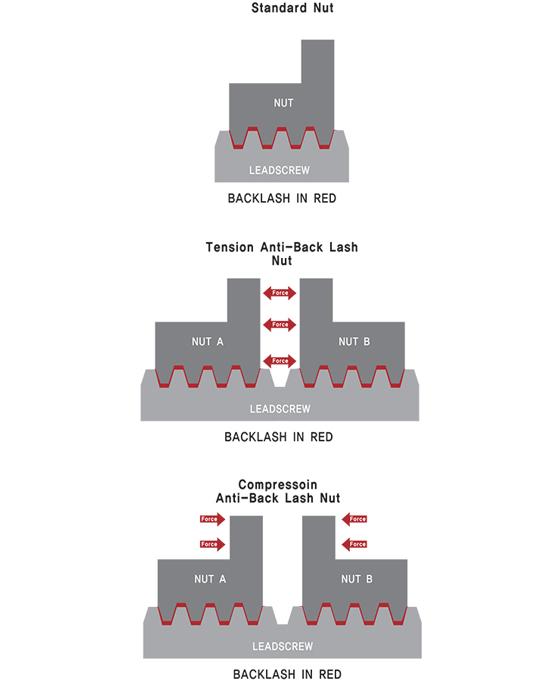
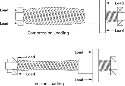
- 11. Tension or Compression Loading
- A load that tends to stretch the screw is called a tension load. A load that tends to squeeze or compress the screw is called a compression load. Depending on the size of the load, designing the screw in tension utilizes the axial strength of the screw versus column loading.
- 12. Axial Load
- A load that exerted at the center line of the lead screw.
- 리드 스크류의 중심선에 가해지는 하중(가장 좋음)
- 13. Static Load
- The maximum thrust load, including shock load, that should be applied to a non-moving screw.
- 14. Dynamic Load
- The maximum recommended thrust load which should be applied to the screw while in motion.
- 15. Backdriving
- Backdriving is the result of the load pushing axially on the screw or nut to create rotary motion. Generally, a nut with an effi ciency greater than 50% will have a tendency to backdrive. Selecting a lead screw with an efficiency below 35% may prevent backdriving. The smaller lead, the less chance for backdriving or free wheeling. Vertical application are more prone to backdriving due to gravity.
- 16. Torque
- The required motor torque to drive just the lead screw assembly is the total of:
- 1. Inertial Torque
2. Drag Torque
3. Torque to move load(Drag Torque = Friction of the nut and screw in motion)
- 17. Lubrication
- The nut material contains a self-lubricating material that eliminates the need for adding a lubricant to the system. The Te on coated screw option also lowers friction and extends life of the system.
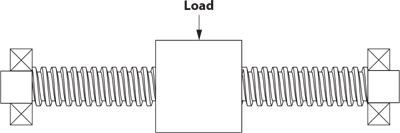
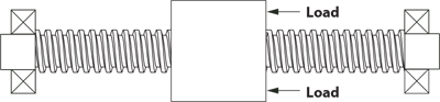
- 18. Fixity
- The performance (speed and effi ciency) of the screw system is affected by how the screw ends are attached and supported.
-
Type of End Fixity Relative Rigidity Critical Speed Factor Critical Load Factor 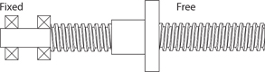
Less Rigid 32 25 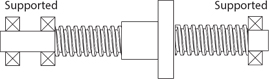
Rigid 1.00 1.00 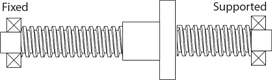
More Rigid 1.55 2.00 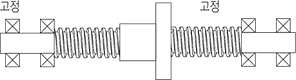
Most Rigid 2.24 4.00
- 19. End Machining of Screw
- Standard metric or English options are available. Custom end machining specifi cations are also available on request.
-
Threaded End 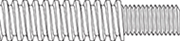
Please refer to
individual
NEMA Size section
for standard
options.
Custom machined
ends are also
available.Example :
UNC end :
#8-32 UNC thread
Metric end :
M4 x 0.7mm threadSmooth end 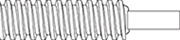
Example :
Ø0.1967˝ ±0.001
Ø5mm ±0.025None 
-
- 20. Column Strength
- When a screw is loaded in compression its limit of elastic stability can be exeeded and the screw will fail through bending or buckling.
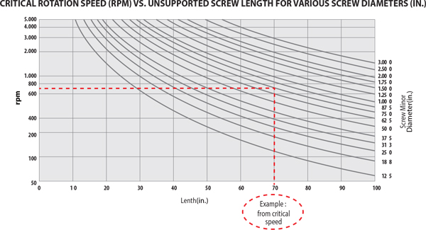
- 21. Critical Speed
- Critical speed is the rotational speed of the screw at which the first harmonic of resonance is reached due to defection of the screw. A system will vibrate and become unstable at these speeds.
- Several variables affect the speed at which a system will reach critical speed:
- 1. The lead of the screw
2. The rotational speed
3. End Fixity
4. The thrust load
5. Diameter of the screw
6. Tension or compression loading - For example, the following chart shows that for a screw with a 3/4 inch diameter and 70 inch length, the threshold for critical speed is 700[rpm]
- 22. Backlash
- Backlash is the relative axial movement between a screw an nut at standstill. It is normal for backlash to increase with wear over time. Blacklash compensation or correction can be accomplished through the application of an anti-backlash nut. Backlash is usually only concern with bi-directional positioning.