

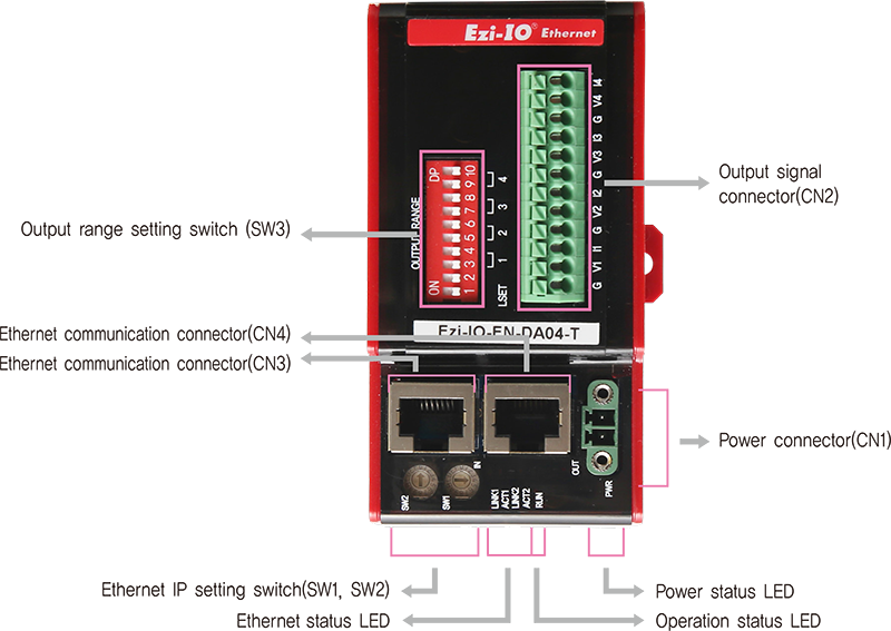
Ezi-IO-EN-AD08-T
Settings and Operation
Switch
- 1. Ethernet IP Setting Switch (SW1, SW2)
-
These switches set the 4th octet of Ethernet IP. The 1st octet,the 2nd octet, and the 3rd octet are set by GUI. If the switches are set to 255(FF), DHCP function is activated, and IP is automatically set, ignoring the set value.
(Please refer to the manual for details.)
e.g.,) In case of SW2 : 5 and SW1 : 7
(5×16) + (7×1) = 87
IP is to be set as 192.168.0.87 
- 2. Output Range Setting Switch (SW3)

- SW3 is a switch for setting the output range. You can set the range with the combination of the switches.
-
• Selecting Input Setting Method
You can select the output setting method with the LSET (SW3.1) switch as follows.SwitchModeLSETSW3.1Description DIP Switch ON Setting output range with DIP switches (SW3.3~SW3.10) Ethernet communication OFF Setting output range with Ethernet communication * Set SW3.1 before supplying power to the module.
* SW3.2 is not used. -
• Output Range Setting
When using the DIP Switch for setting (SW3.1 = ON), the output range is set as shown in the table below.SwitchOutput RangeCH1 CH2 CH3 CH4 SW3.3 SW3.4 SW3.5 SW3.6 SW3.7 SW3.8 SW3.9 SW3.10 0~5V OFF OFF OFF OFF OFF OFF OFF OFF -10~10V OFF ON OFF ON OFF ON OFF ON 0~20mA ON OFF ON OFF ON OFF ON OFF 4~20mA ON ON ON ON ON ON ON ON * Output range of 1~5V and 0~10V can only be set by Ethernet communication.
LED Indications
- 1. Power Status LED
-
Name Color Status Description PWR Red OFF Power is OFF ON Power is ON
- 2. Operation Status LED
-
Name Color Status Description RUN Green OFF Abnormal Operation Blinking Normal Operation
- 3. Ethernet Status LED
-
Name Color Status Description LINK1, LINK2 Green OFF Link not Established ON Link Established
- 4. Ethernet Status LED
-
LED Color Status Description ACT1, ACT2 Yellow OFF Stand-by Flickering In Operation
Connector
- 1. Power Connector (CN1)
-
No. Fuction I/O 1 DC24V Input 2 GND Input 
- 2. Output Signal Connector (CN2)
-
No. Name Fuction I/O 1 G Analog GND Output 2 V1 Voltage Out 1 Output 3 I1 Current Out 1 Output 4 G Analog GND Output 5 V2 Voltage Out 2 Output 6 I2 Current Out 2 Output 7 G Analog GND Output 8 V3 Voltage Out 3 Output 9 I3 Current Out 3 Output 10 G Analog GND Output 11 V4 Voltage Out 4 Output 12 I4 Current Out 4 Output 
- 3. Ethernet Communication Connector (CN3, CN4)
-
NO. Function 1 TD+ 2 TD- 3 RD+ 4 ---- 5 ---- -
NO. Function 6 RD- 7 ---- 8 ---- Connector
hoodF.GND 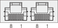
Accessories - Connectors
-
Purpose Item Part Number Manufacturer Power (CN1) Terminal Block MC421-38102 DECA - ※ The connectors above are supplied with the product. If you are using other parts, please make sure they meet the specifications.
Options - Ethernet Cable
-
Purpose Part Number Length [m] Remarks Ethernet Connection
(CN3, CN4)CGNR-EC-001F
CGNR-EC-002F
CGNR-EC-003F
CGNR-EC-005F1
2
3
5· STP(Shielded Twisted Pair) Cable
· Category 5e or higher
· Maximum Length: 100m
· Normal Cable - ※ If you need cables with length(in units of 1m) not listed on the table or robot cables, please contact FASTECH for more information.