


Settings and Operation
Status LED
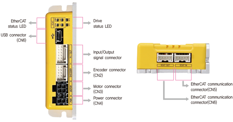
- 1. EtherCAT Status Monitor LED
-
Name Color Function Explanation RUN Green OFF State INIT or Power OFF Blinking State PRE-OPERATIONAL Single Flash State SAFE-OPERATIONAL ON State OPERATIONAL Flickering State BOOTSTRAP ERR Red OFF No Error or Power OFF Blinking Invalid Configuration Single Flash Local Error Double Flash Watchdog Time Out LA1/
LA2Green OFF Link not Established ON Link Established Flickering Link Established and in Operation 
- 2. Drive Status LED
- In the case of Ezi-STEPⅡ EtherCAT MINI series products, LED can be checked by LED color, lighting, On/Off and blinking.
-
Status LED Disable ST1 :
ST2 :ST1 light flashing, ST2 light off Enable ST1 :
ST2 :ST1 light on, ST2 light off In motion ST1 :
ST2 :ST1 light on, ST2 light on Alarm ST1 :
ST2 :ST2 light flashing repeatedly as many as alarm number 
- ◆ Protection functions and LED flash times
-
Times Protection Conditions 1 Over Current Error The current through power devices in drive exceeds 4.8A 2 Over Speed Error Motor speed exceeds 3,000 [rpm] 5 Over Temperature Error Inside temperature of drive exceeds 85℃ 6 Over Regeneratived Voltage Error Back-EMF is higher than 48V 7 Motor Connect Error The drive does STEP ON without connection of the motor cable to drive. 12 ROM Error Error occurs in parameter storage device(ROM) -
Alarm LED flash
(Ex, Over Speed error)
Connector
- 1. Input/Output Signal Connector(CN1)
-
NO. Function I/O 1 EXT_24VDC Input 2 EXT_GND Input 3 BRAKE+ Output 4 BRAKE- Output 5 LIMIT+ Input 6 LIMIT- Input -
NO. Function I/O 7 ORIGIN Input 8 Digital In1 Input 9 Digital In2 Input 10 Digital In3 Input 11 Digital Out1 Output 12 Digital Out2 Output 
- 2. Encoder Connector(CN2)
-
NO. Function I/O 1 A+ Input 2 A- Input 3 B+ Input 4 B- Input 5 Z+ Input -
NO. Function I/O 6 Z- Input 7 5VDC Output 8 GND Output 9 F. GND ---- 10 F. GND ---- 
- 3. Motor Connector(CN3)
-
NO. Function I/O 1 A Phase Output 2 B Phase Output 3 /A Phase Output 4 /B Phase Output 
- 4. Power Connector(CN4)
-
NO. Function I/O 1 24VDC Input 2 GND Input 
- 5. EtherCAT Communication Connector(CN5, CN6)
-
NO. Function 1 TD+ 2 TD- 3 RD+ 4 RD- 5 F.GND 
- 6. USB Connector(CN7)
-
NO. Function 1 VBUS 2 D- 3 D+ 4 ---- 5 GND 
Connector Specifications
- Connector specifications for cabling to drive.
-
Purpose Item Part Number Manufacturer EtherCAT Communication
(CN5, CN6)Housing
TerminalPAP-05V-S
SPHD-001T-P0.5JST Power
(CN4)Housing
Terminal43025-0200
43030-0001MOLEX Motor Drive Side
(CN3)Housing
Terminal43025-0400
43030-0001MOLEX Motor Side Housing
Terminal5557-04R
5556TMOLEX Encoder Side Drive Side
(CN2)Housing
Terminal501646-1000
501648-1000(AWG 26~28)MOLEX Signal
(CN1)Housing
Terminal501646-1200
501648-1000(AWG 26~28)MOLEX - ※ Above connector is the most suitable product for the drive applied. Another equivalent connector can be used.