


Input Signal
- Input signals of the drive are all photocoupler protected. The signal shows the status of internal photocouplers [ON: conduction], [OFF: Non-cond
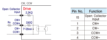
- ◆ CW, CCW Input
- This signal can be used to receive a positioning pulse command from a user host motion controller. The user can select 1-pulse input mode or 2-pulse input mode. The input schematic of CW, CCW is designed for 5V TTL level. When using 5V level as an input signal, the resistor Rx is not used and connect to the driver directly. When the level of input signal is more than 5V, Rx resistor is required. If the resistor is absent, the drive will be damaged. If the input signal level is 12V, Rx value is 680ohm and 24V, Rx value is 1.8Kohm.

- Alarm Reset signal line is also used of r Motor Free signal.
- ◆ Motor Free Input
- This input can be used only to adjust the position by manually moving the motor shaft from the load-side. By setting the signal [ON], the drive cuts off the power supply to the motor. Then, one can manually adjust output position. When setting the signal back to [OFF], the drive resumes the power supply to the motor and recovers the holding torque. When driving a motor, one needs to set the signal [OFF]. In normal operations set the signal [OFF] or disconnect a wire to the signal.
- ◆ Alarm Reset Input
- When a protection mode has been activated, a signal to this Alarm Reset input cancels the Alarm output. By setting the alarm reset input signal [ON], cancel Alarm output. Before cancel the Alarm output, have to remove the source of alarm.

- [Caution]] If Alarm Reset input signal still remains [ON], motor will be Free state. Keep in mind to change [ON]→[OFF] state.
Output Signal
- As the output signal from the drive, there are the photocoupler outputs (Alarm, Run/Stop). The signal status operate as [ON : conduction], [OFF : Non-conduction] of photocoupler not as the voltage level of signal.

- ◆ Alarm Output
- The Alarm output indicates [OFF] when the drive is in a normal operation. If a protection mode has been activated, it goes [ON]. A host controller meeds to detect this signal and stop sending a motor driving command. When the drive detects an abnormal operation such as overload of overcurrent of a motor, it sets the Alarm output to [ON], flash the Alarm LED, disconnects the power to a motor, and stops the motor, simultaneously.
- ◆ Run/Stop Output
- Run/Stop Output state is [ON] when motor positioning is completed. It operates reversely compare to Normal mode, when you set inverse mode.

Parameter Settings GUI
[User Interface]
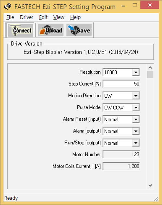
- Ezi-STEP BT drive utilizes various parameters for operation and some parameters can be changed upon the needs of the user. Ezi-STEP BT provides Drive Setting Program for more convenient use. The screen shot in right side is the sample of Drive Setting Program which is used for drive setting and parameter change. User can change and set the parameter such as Resolution, Stop Current, level of Alarm Reset, Alarm, Motion Direction and so on. By using this drive setting program, user can find the optimal condition to Ezi-STEP BT to fit with the user's own system. Please be noticed that connection for drive setting program shall be done when the Ezi-STEP BT is disable staus for safety reason.
- ※ Parameter setting program can be downloaded from website. (www.fastech-motions.com)
- ※ Parameter setting program can support Window 7/8/10.
- ※ Parameter setting program(GUI) can be updated without notice to improve the performance and convenience of user.